Devlog #13 - One Colorful Shader
I recently added a new level to Sound Horizons : One Colorful Grid. If this name rings a bell, that's because it comes from the game I made before Sound Horizons, the one that actually inspired it. It was the occasion to remake it into something more polished and visually pleasant. I kept the same music (only adding an extra layer for the end), but created new visuals for it.

Those are the subject of this post. The One Colorful Grid level is made of thousands of cubes floating in space. Some are used for the ground, others for the ceiling, some are organized in columns, and others form trails passing above the player's view. And most importantly, all of them react to the music's beats and the game's actions!
All of this is handled by a single shader. That's right: cube positions, movement, scale, colors, all of those are declared in one gigantic Unity Shader Graph.
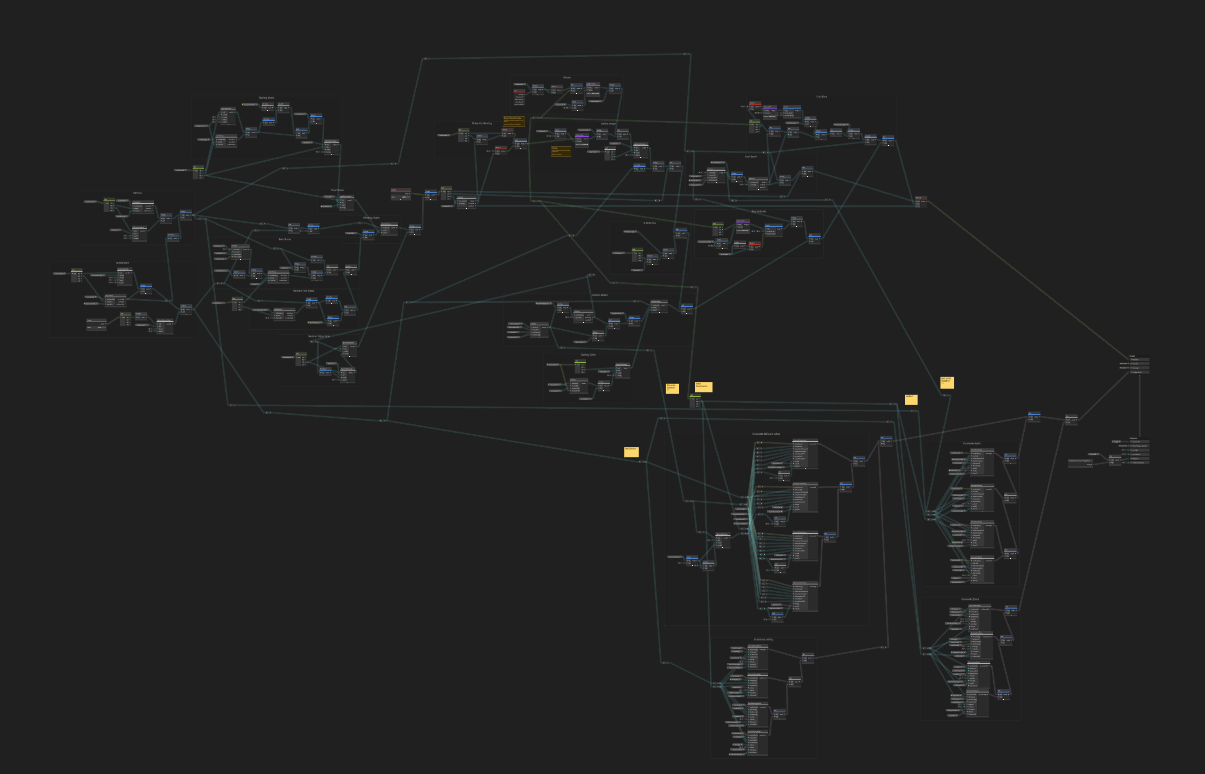
Now I won't detail all of its content. But I'll explain the basis and provide some kind of tutorial to allow you to create similar landscapes.
1. Instancing the cubes
This part is already documented by plenty of resources, so I won't enter too much into the details. One of the resource that I consulted a lot was Tarodev's video How to Render 2 Millions Objects at 120 FPS. It comes with a helpful git repo in the description!
To add this amount of cubes in the scene, I used Unity's GPU Instancing. Basically it's a shortcut to render several meshes using directly Unity's graphics API. They have no logic or collision, they are just rendered in the scene. This is an efficient way to display a large quantity of elements.
The function to use for that is Graphics.RenderMeshInstanced. It takes:
- A
RenderParamsinstance, associated to a Material, that will be used to render each mesh instance - The Mesh to render
- The index of the sub-mesh to render. I our case, we don't have any, so it's just
0 - An array of
Matrix4x4, each indicating the position, rotation and scale of the instance
So the first order of business is to prepare this array. This is done only once, generally at the start. I placed all the cubes on a flat grid. The height will be managed by the shader only. I don't update the rotation, so I leave it to Quaternion.identity. As for the scale, it will determines the size of a cell: the larger it is, the larger will be the grid.
// Assume that the variables that are not declared are attributes of the class

materialProperties = new MaterialPropertyBlock();
renderParams = new RenderParams(material);
matrices = new Matrix4x4[width * depth * height];

int iterator = 0;
float leftSide = transform.position.x - cubeSize * width / 2f;
for (int x = 0; x < width; x++) {
  for (int y = 0; y < depth; y++) {
    for (int z = 0; z < height; z++) {
      Vector3 position = new Vector3(leftSide + x * cubeSize, transform.position.y, y * cubeSize);
      matrices[iterator] = Matrix4x4.TRS(position, Quaternion.identity, Vector3.one * cubeSize);

      iterator++;
    }
  }
}
Then we need to call the Graphics.RenderMeshInstanced in the Update method. Yes, this has to be done on each frame. Fortunately, it doesn't cost much for the CPU.
void Update() {
  Graphics.RenderMeshInstanced<matrix4x4>(renderParams, mesh, 0, matrices);
}
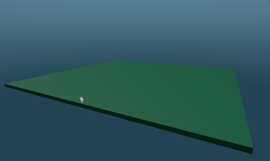
This gives us a flat plane made several cubes. Not really exciting yet. Let's give it some terrain height!
2. Shaping the terrain
We'll use a vertex shader to move slightly the cubes on the Y axis to gives some roughness to the terrain. In this article, this shader will be made with Unity Shader Graph. But you can as well write your own in HLSL if you know how to do so.
First, create the Shader (Create > Shader Graph), then the Material using it (right click on the shader, Create > Material). Then assign this shader to the C# component so that it will be used for the rendering (see code above).
Now, the goal here is to move the vertex to update the cubes' positions. For this we'll use a Perlin noise, using the cube's coordinate as UV input it to determine the height to apply. However, if we directly use the World Position in our shader, what we'll obtain is the vertex coordinate, not the cube one! This will result in different transformation applied to each vertex, which will deform the cube. We don't want that. We want for each cube to use a single coordinate, so that all vertex have the same transformation.
This "cube coordinate" is an information that we will gives to the shader from the C# logic. In the shader, create a Vector property coordinates. Since we're using the same Material for all cubes, we need to set this property scope to "Hybrid per instance" so that each cube uses a different one.

Then, in our code, we add a little bit of logic during the array preparation to write the coordinates of each cubes:
List<vector4> coordinates = new List<vector4>();
// [...]
for (int x = 0; x < width; x++) {
  for (int y = 0; y < depth; y++) {
    for (int z = 0; z < height; z++) {
      //[...]
      // Warning: I used the Z index for height. Let's pretend we're in Blender, ok?
      coordinates.Add(new Vector4(x, y, z));

      iterator++;
    }
  }
}
materialProperties.SetVectorArray("_coordinates", coordinates);
The SetVectorArray method of a MaterialPropertyBlock allows to set an instanced property for each meshes. It uses the index to associate each value to an instance. So we have to make sure that the coordinates are in the same order as the Matrix4x4[].
Now that we have unique coordinates for each cube, we can use that property as UV in the shader. The terrain height is generated with a Perlin Noise, to which we apply a strength and a scale given as global properties to the Material. The result is then added to the vertex position (on the Y axis).
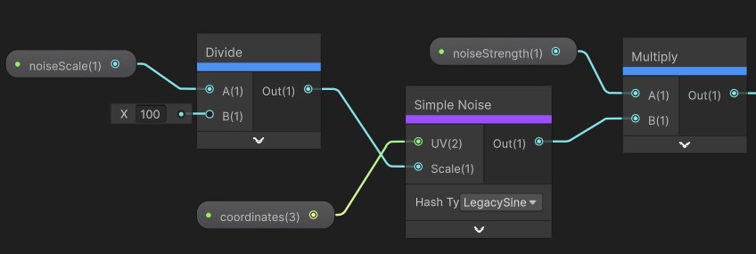
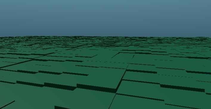
However we are not done yet! We actually don't want to directly use the coordinates as UV. This has to do with the next part, where we'll manage a key element of our terrain.
3. Infinite scroll
The camera view in One Colorful Grid seems like it's moving forward, as if it navigates through an infinite field.
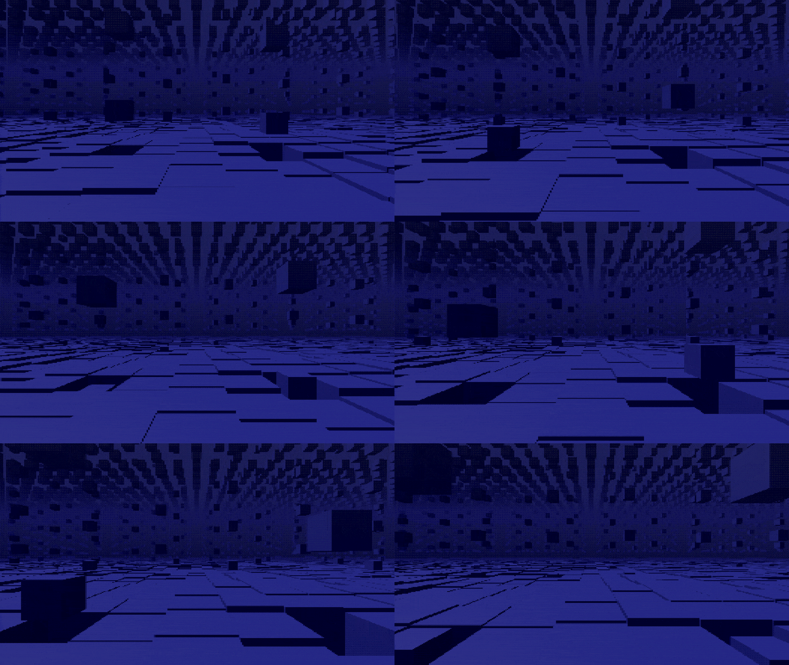
That is, of course, purely an illusion. The camera stays in the same position, it is actually the terrain that moves. More exactly, it's the cubes themselves that are translated by the shader.
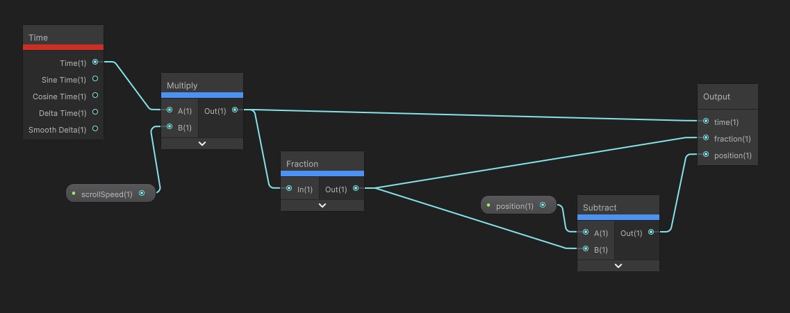
Creating a translation in a shader is pretty simple. Using the Time node combined with a Fraction, multiplied by a speed, we add a value between 0 and 1 to the Z axis of the vertex. This makes them move of one "unit" (one cell, equal to the cube's size).
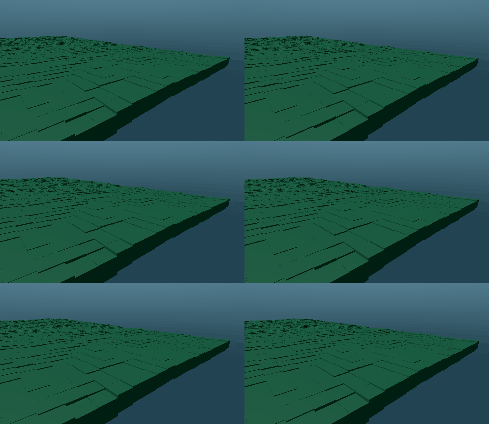
However, with our terrain effect in place, this doesn't really look like a scroll.
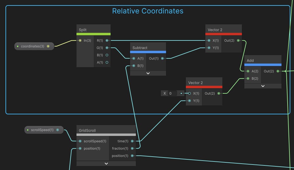
To make it work, instead of using the coordinates directly on the noise, we have to compute relative coordinates from the scroll. Coordinates which will increment with time: a cube that is at position X will first "represents" the terrain's position 0, but once it has done a complete cycle (translated from 0 to 1 and back to 0), it will represents the X+1 coordinates, then X+2, X+3, and so on. We thus have to read the time and fraction values from the scroll to then update the coordinates before sending them to the Perlin noise.
And with this, the illusion of a moving terrain is finally working!
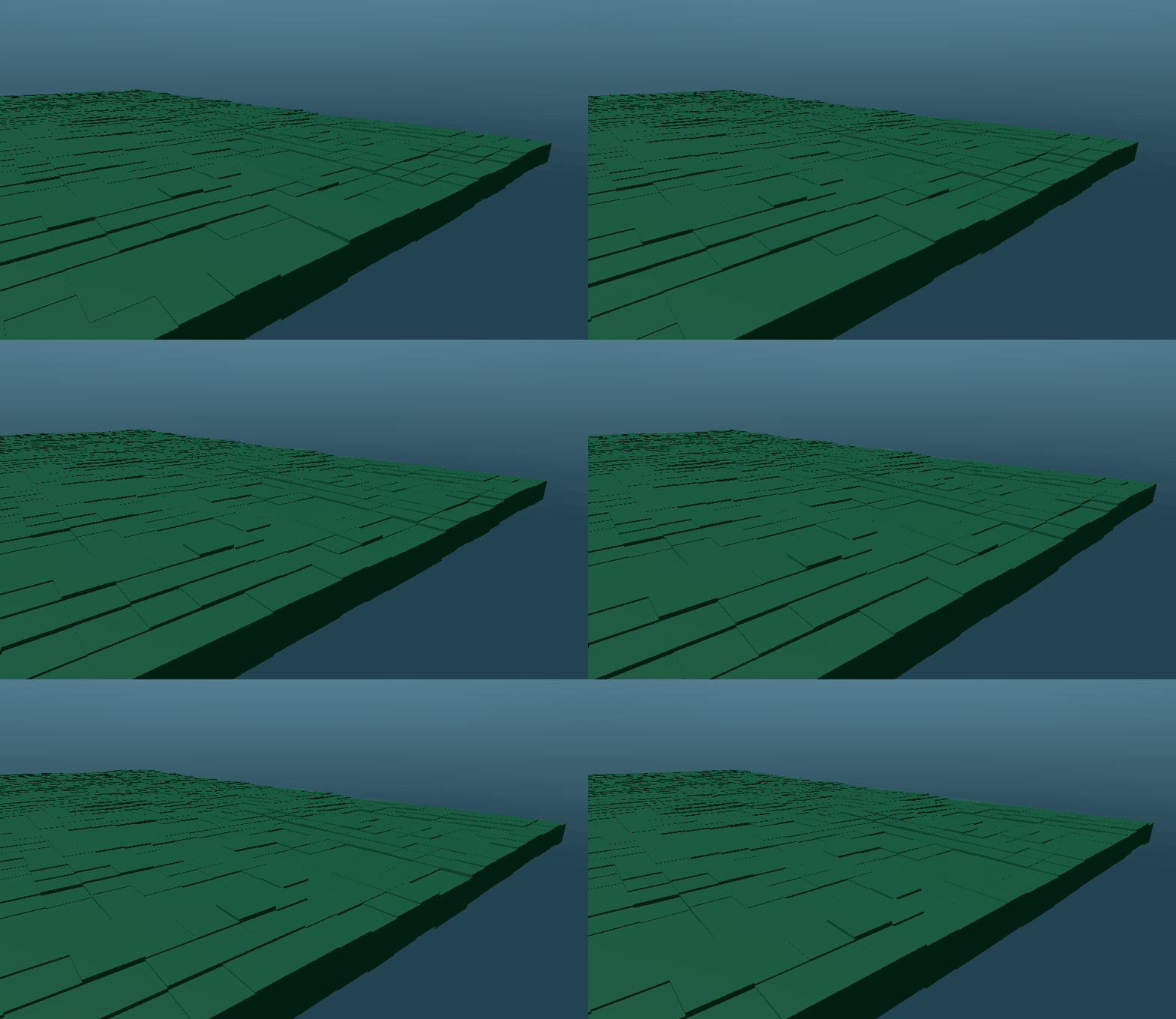
4. Columns
So far, we've been making only a flat terrain. It is time to use a bit the vertical axis and display some of the cubes on the other layers. Our goal will be to create columns of cubes placed every 4 cells.
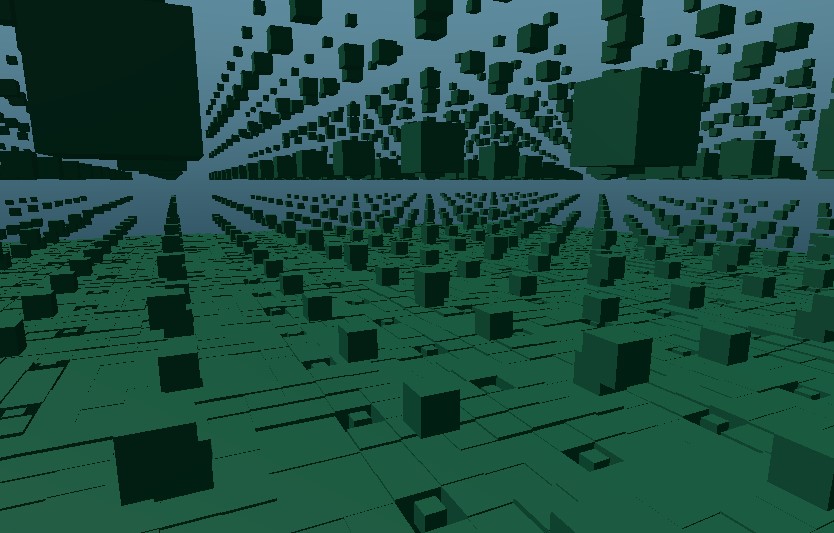
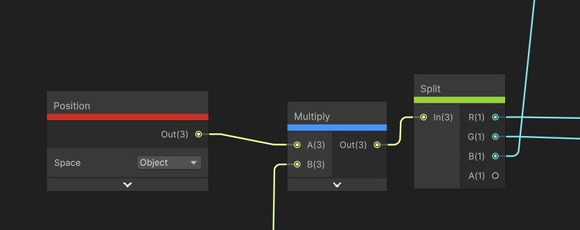
To hide or show a cube, I'm using their scale. At scale 0, they will be completely invisible. The cubes on the floor will remain at scale 1, and a global property will determine the scale of the cubes within the columns. To scale a mesh from a shader, you just have to multiply the vertex position. Naturally, this must be done before the translation.
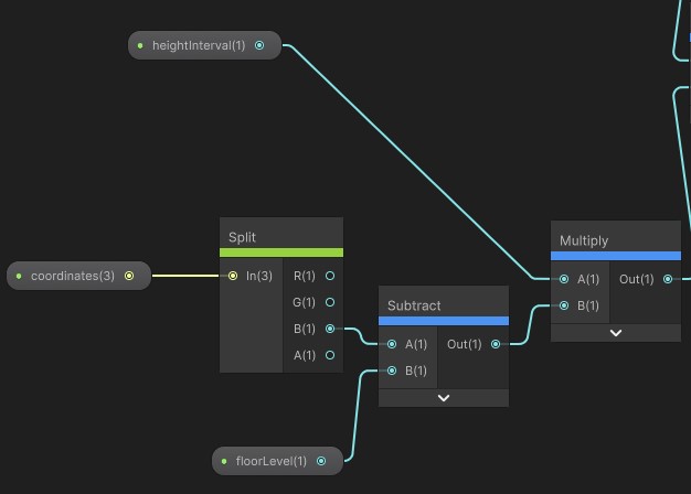
For the height, it's pretty similar to what we have done with the terrain. Reading the z value of coordinates (which represents the height, remember), we multiply it by a global property heightInterval that determines the distance between two cubes in a column. This can then be added to the Y value of the vertex position.
The tricky part is now to target the columns (on the X and Y value of the cube's coordinates). In order to display the columns only every 4 cubes, we have to use the modulo operation. Given coordinates (x, y), if x % 4 == 0 and y % 4 == 0, then the cube is part of a column, and must be scaled as such. Otherwise it is either hidden or displayed at a regular size if it's on the floor.
But remember the adaptations we had to make because of the scrolling! This is similar here. The columns Y coordinate will move with time, and need to be shifted. At cycle 0, the operation to make is y % 4 == 0. Then it is y % 4 == 3, then y % 4 == 2, and so on until we're back at 0 again.
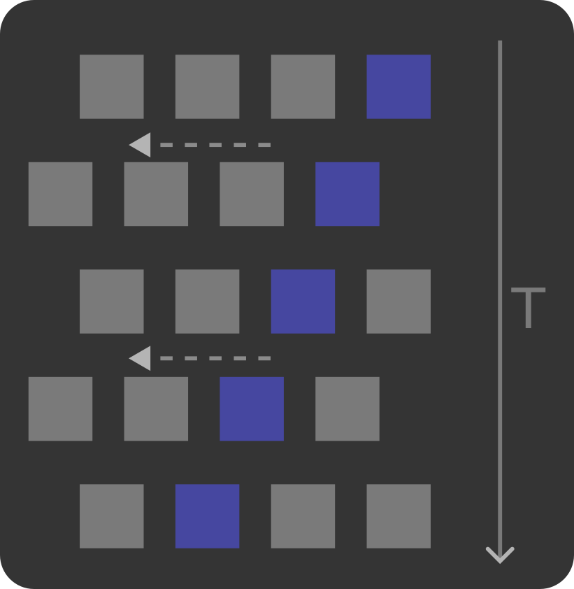
Here is how I implemented it in Shader Graph:
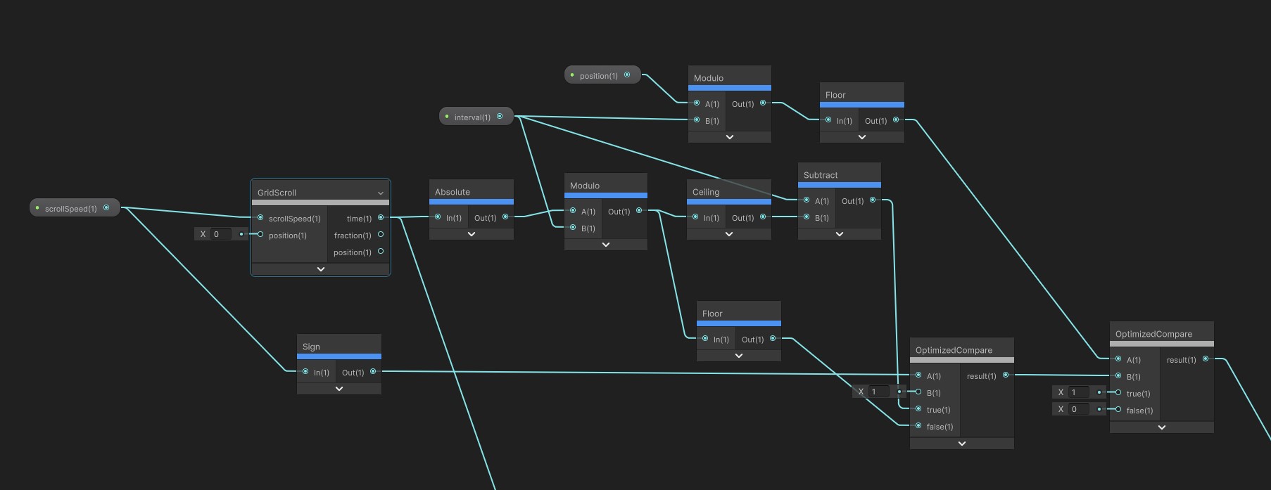
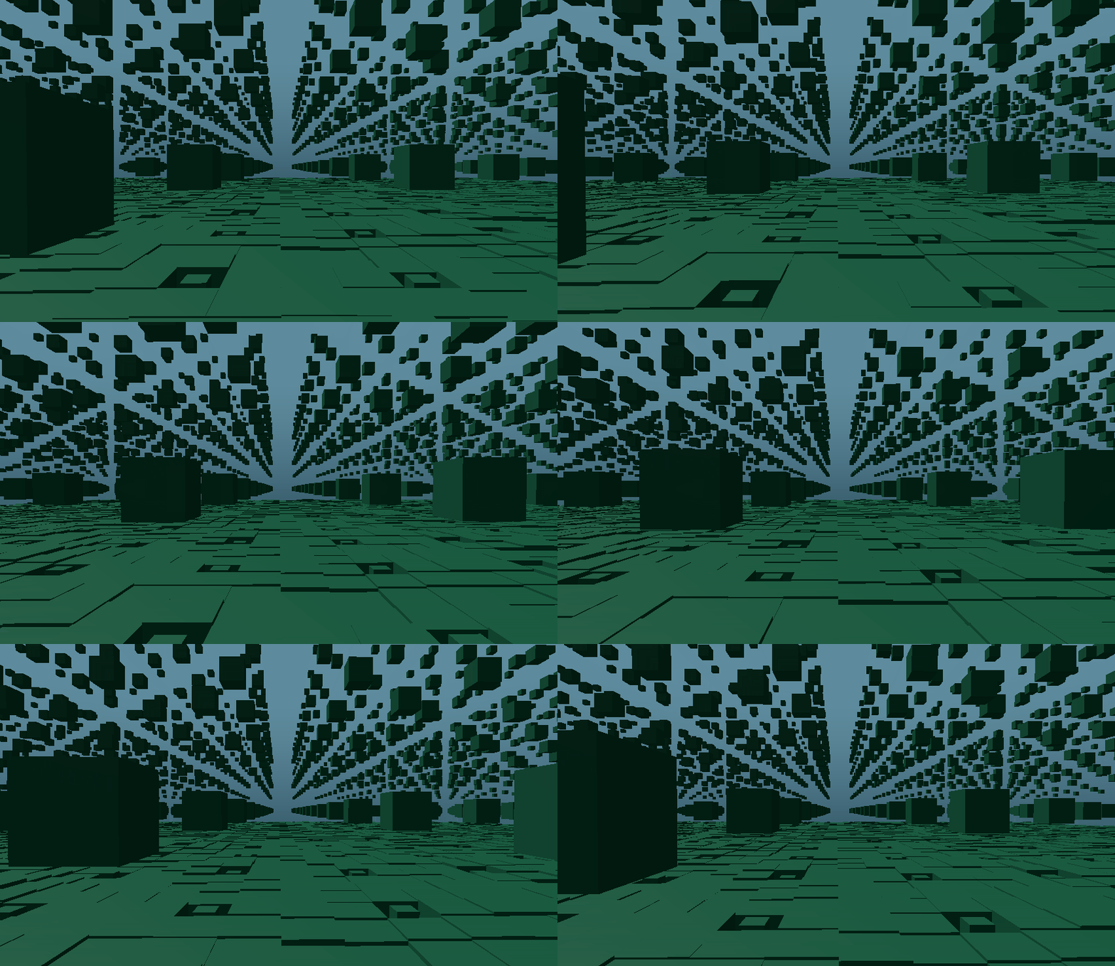
And now that we can target specific blocks in the scrolling, we can pretty much do anything! For example, the horizontal trails use the same logic: they appear every 3 cells, with a height randomized with another Perlin noise. The column's Y scrolling and the trail's X scrolling are handled in the same way than the terrain's Z scrolling. With only the direction determined by their position, so that it alternate every two of them (making them scroll backwards requires only to multiply their speed by -1). Of course there are some mathematics subtleties at every step. But those are only specifics. For the global logic, you now have all the ground basis to do whatever you want.
Note : On Branching
As I explained, to determine the scale and position of a block, I have to check its coordinates and see if it satisfies certain rules. This could be done with Conditions and logic operators. But shader are not performant with branching. And as you might guess, there is a lot of conditions in this shader!
So to optimize that, I created optimized branching nodes to rely on multiplications rather than branches. Multiplying by 0 is much faster for the GPU that testing a branch! To compare two values A and B, and obtain X if they are equal or Y if not, the operation is:
d = min(1, ceil(abs(A - B))) // 0 if equal, 1 otherwise
res = X * (1 - d) + Y * d
In Shader Graph, it is done like so:

Generally, for any condition, I use 1 as true and 0 as false. The operator and is replaced by multiplication, and or by addition.
5. Animations & colors
Finally let's talk a bit about how the animations are handled. Some music and game events animate the cubes position and scale. For impacting the shader, once again, we use global material properties. They are updated from a C# logic in a component, using Tweens. For Sound Horizons, I already had created utilities to interpolate values between materials to animate them. As you can guess, the shader in One Colorful Grid uses a lot of properties.
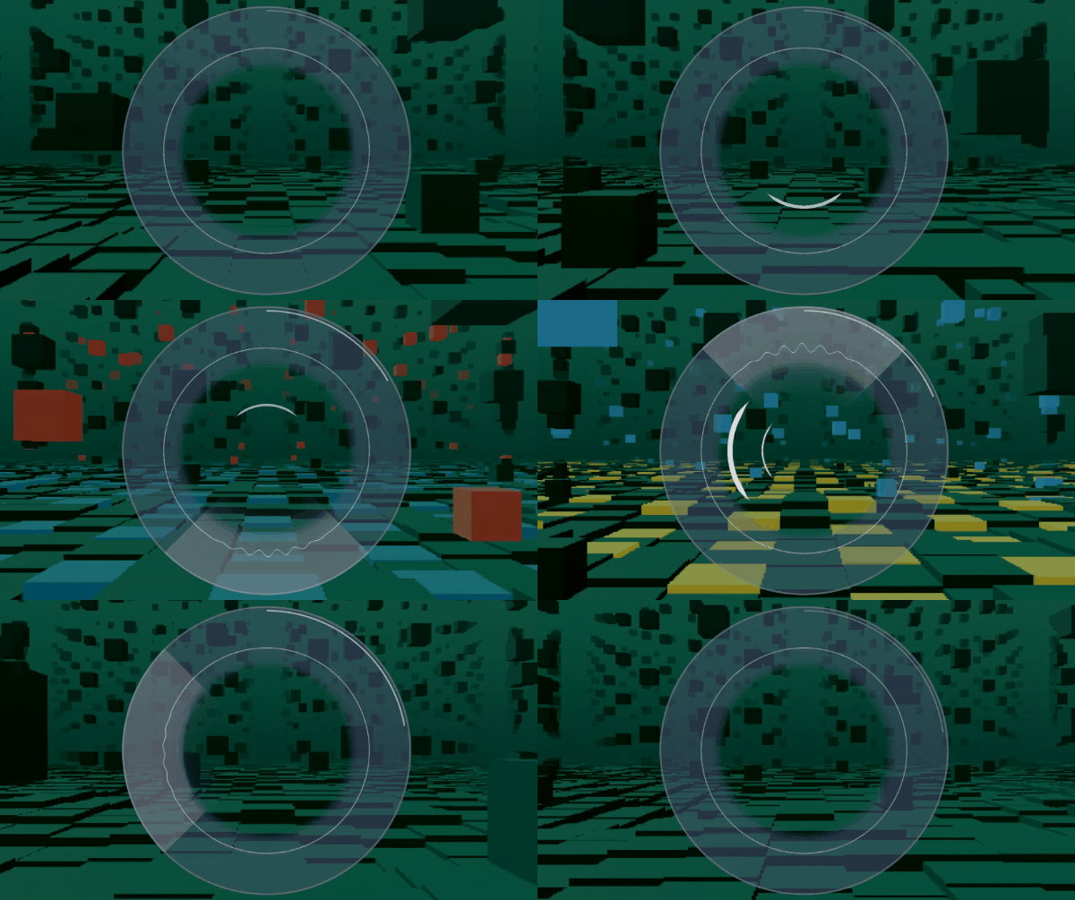
Once again, all of these properties animate only specific cubes. Like for the columns, I filter them first with conditions on their coordinates. Sometime it animates only the columns, sometime one every two cells, sometime alternating... One particular case is the colorization of the blocks in the column. I didn't want them to be regular. There are four different colors (each one corresponding to one direction in the game), and they are positioned in this particular order : on the first column, it is at index 1 (first in every 4 blocks). Then on second, at index 3, then 2, and finally 4. I thus use an array with values [0,2,1,3] to determine which index to use. But how can we declare an array in Shader Graph? Answer: with a gradient.
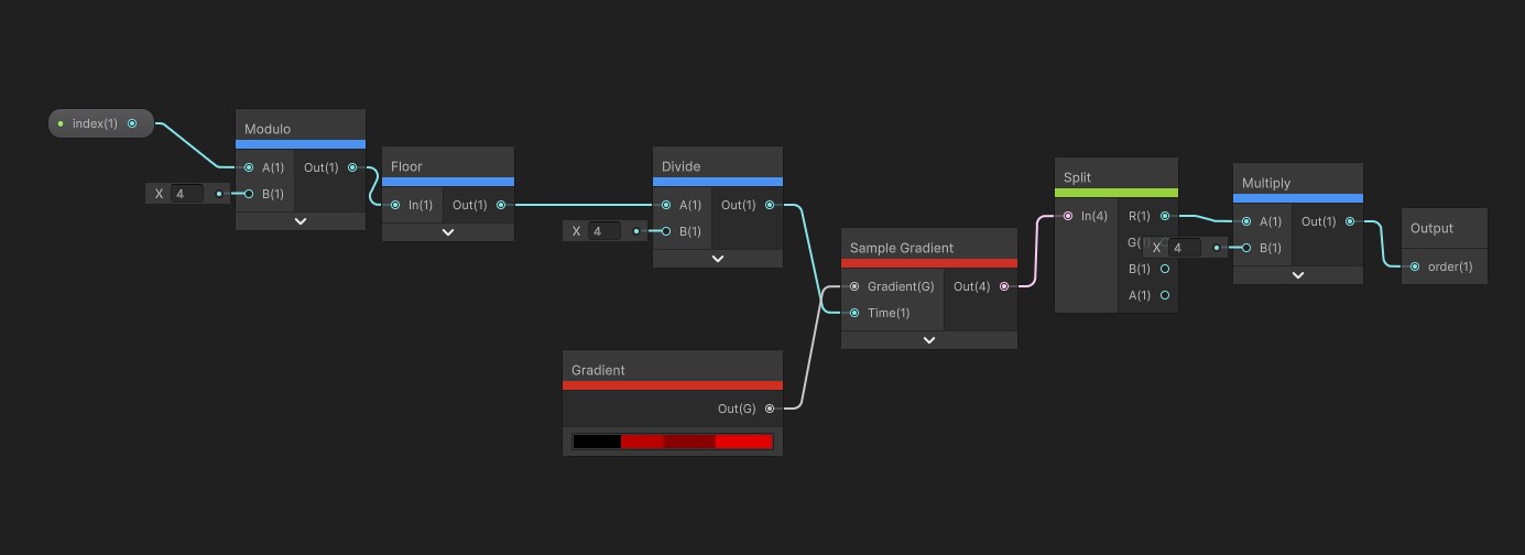
I only use the R value of the color to set a value between 0 and 1. To read from this array, I use a SampleGradient node, dividing my index by the array's length (4) to set it between 0 and 1, and then multiplying the result to the values maximum (4) so that it is on my scale.
After selecting blocks, I apply either a scaling transformation, a translation, or a color shift. Once again, scaling is done by multiplying the vertex position, translating by adding a value to it.
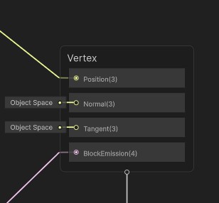
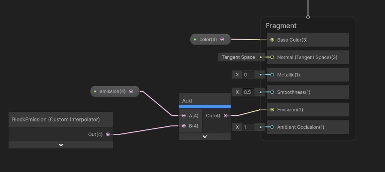
As for the color, it is done by the fragment shader, by writing on the Emission. But wait! While the vertex shader runs for all vertex, the fragment shader runs for every fragments (approximately every pixel). Given all the computation we have to do to determine if a block must be animated or not, this will likely have a huge cost! Extremely unnecessary since we only want a single color for of a cube. So to optimize this, the emission is computed from the vertex shader, and passed to the fragment shader as a Custom Interpolator.
Is this actually optimized?
This is quite an ambitious shader. It manages an entire 3D grid of cubes, applying for each one different scales and animations. It's almost a voxel engine! On the plus side, it allowed me to display a very large quantity of objects, and animate them using only the GPU. But even graphics cards have their limits. And there's a lot of operation in this shader. What are the results?
Well, on my gaming machine, the game runs at 120 FPS. It is less than what it could achieve on the other level, but that's decent enough. On my low spec laptop however, which I use primarily for writing or programming, it gets down to 30 fps. Still enough to be able to play, but a significant loss given that the previous level managed to have more than 60 FPS. On an average device used for gaming though, I think the 60 FPS should be guaranteed. In any case, this landscape consumes a non negligible quantity of GPU resources, making it less performant than the rest of the game. A pity for a rhythm game! It doesn't even display that many elements. So how could it be improved?
I already made some optimizations. Like I said earlier, I replaced every conditions with mathematics operation to avoid branching. I also adjusted the C# algorithm to definitely remove some cells that are actually never displayed (not part of a column or trail). No need to add computation for them, right? And finally, I limited the size of the grid as much as I could, using distance fog, some kind of "scaling fade out" for the cubes at the edges of columns, and a low camera field of view.
Then there are some more radical refactoring that could have been implemented. One of them that I tried is to use a Compute shader rather than a vertex one. Rather than computing the cube's position and scale for every vertex, we could do that only once per cube, right? I gave it two days to see if the conversion could be done without too much struggle. But it brought its own kind of issues before I even completed the setup! At the time the level was already finished, it wasn't worth to spend so much time into a solution that had no guarantee of significant improvement. It could work in theory, but I don't know how much it would change performances.
Another more basic approach would be to use different Materials and shaders for each element. One Material for the ground, one other for the columns, one for the trails… I actually don't need to do everything from the GPU, a C# logic could very well handle the scrolling! There are chances that it would provides a significant gain (on top of more isolated and understandable algorithms). The reason why I made a single shader for everything was that I wanted to use it as a playground. I didn't have precise directions when I started working on the level. So I created a 3D grid, and tried different combinations that seemed visually interesting! The resulting shader is purely empiric. But if I had these objectives in mind from the start, surely I would have found easier solutions to implement them.
Finally, someone suggested to me that I could have used BatchRendererGroup. I discovered it only after having implemented the level, and indeed it seems to correspond exactly to my needs. They even use a field of colored cubes as example! Implementing it seems radically different than my approach though, so I can't really tell you much about them. But it might be something worthy to check out.
In the end I'm still happy with what I achieved in One Colorful Grid! I wasn't sure where I was going exactly when I started, but it eventually turned into some pretty neat visuals. And I actually learned some new things about shader logic. My next goal would be to step away from Shader Graph, and try to directly write some shader in HLSL. Or even create shader for Godot, and learn what can be done with that engine! I don't have exact plans yet, but I'll probably make prototype or small games to experiment with those.
Get Sound Horizons
Sound Horizons
A procedural rhythm game with interactive music
| Status | In development |
| Author | Itooh |
| Genre | Rhythm |
| Tags | 3D, Atmospheric, Low-poly, Procedural Generation |
More posts
- Final Stage Difficulty UpdateJan 02, 2025
- Colorful Grid UpdateNov 22, 2024
- Accessibility UpdateSep 30, 2024
- Sound Horizons is out today!Sep 18, 2024
- Devlog #12 - Score in a procedural worldJul 08, 2024
- Devlog #11 - Menus Part 2Jun 17, 2024
- Announce trailer and official store pagesJun 06, 2024
- Sound Horizons Beta is available for play-testApr 29, 2024
- Devlog #10 - Loops and circlesApr 03, 2024

Leave a comment
Log in with itch.io to leave a comment.