
Sound Horizons
Devlog #9 - Shader recipe for low-poly mountains in Unity
Here is some kind of a "good" news: I've remade the procedural generation of the mountain (again)! You might ask, how is this a good news? Wasn't this done already? Well, yes, but if you've read the devlog entry about it, you might remember that it had some performances issues. Because the mountains where created by script, they relied a lot on the CPU. It could be quite expensive, especially for calculating the noise! And indeed, theses performances issues became very problematic recently when I added the animations. The game had visible framerate loss, and even small freezes! Which, for a rhythm game, is a major problem. This was making the game unplayable, especially on the more difficult layers!
I suggested as an alternative solution to use shaders to generate the mountains. Since today I'm pushed into a corner, I had to finally do it. These new mountains rely now only on GPU, and the game is smooth again!

However it was not as easy as I thought. Alright, I knew it would be an ambitious task. But there was some pitfalls along the way. So here is a special entry for this devlog: I'll show you step by step how these mountains work. So that you too can create such landscape in Unity! And also for you to avoid the problems that I encountered along the way. Because boy do I wish I had more resources to help me in this journey!
Step 1: Plane generation
Before we talk about shaders, we need to write some logic in C#. This is the part I've already covered in my previous devlog entry. So I won't get too much into details. For a more in-depth explanation, you can read the article I took inspiration from.
You need a plane for modelling your terrain. But not any kind of plane: a plane with triangles! If you take the default Unity plane, you'll end up with faces shaped like squares, which doesn't convey a low-poly aesthetic. To make such a plane, there's a lot of options. The simplest might be to create one by hand with Blender, Maya, or whatever 3D tool you use! Make sure that it has enough triangle faces, and you're good to go. You will have to alter it by code though, but this will be for a later part.
However if, like me, you want to generate the plane by code, here is basically how you can do: create an object with a Mesh Filter and a Mesh Renderer. Then add a new component with a custom Script (let's call it TerrainGenerator). This script will use two methods to generate the plane:
- GeneratePolygon : This won't create a mesh, but it will calculate the "theoretical" positions of its vertex. It uses the library TriangleNet to do so. The points can be either completely random, or disposed at a regular interval with a Poisson distribution. For more details about how it works, refer to the article above.
- GenerateMesh : This uses the result of the previous method to instantiate the mesh in the scene. It iterates through each triangle one by one, and for each of its 3 points, creates a vertex on the appropriate coordinates. It then inserts them into a new mesh.
This is what my GeneratePolygon function looks like:
private Polygon polygon;
private TriangleNet.TriangleNetMesh mesh;
private UnityEngine.Mesh terrainMesh;
private List<Color> colors;
// Terrain config is a custom Scriptable Object I use to specify terrain properties, like size, number of vertices, height...
public TerrainConfig terrainConfig;
public void GeneratePolygon() {
  polygon = new Polygon();
  polygon.Add(new Vertex(0, terrainConfig.sizeY));
  polygon.Add(new Vertex(terrainConfig.sizeX, terrainConfig.sizeY));
  polygon.Add(new Vertex(0, 0));
  polygon.Add(new Vertex(terrainConfig.sizeX, 0));
  if (terrainConfig.randomPoints)
  {
    for (int i = 0; i < terrainConfig.pointsDensity - polygon.Count; i++)
    {
      float x = UnityEngine.Random.Range(0f, terrainConfig.sizeX);
      float y = UnityEngine.Random.Range(0f, terrainConfig.sizeY);
      polygon.Add(new Vertex(x, y));
    }
  }
  else
  {
    // Poisson distribution
    List<Vector2> points = PoissonDiscSampling.GeneratePoints(terrainConfig.minDistancePerPoint, new Vector2(terrainConfig.sizeX, terrainConfig.sizeY), terrainConfig.rejectionSamples);
    foreach (Vector2 p in points)
    {
      polygon.Add(new Vertex(p.x, p.y));
    }
  }
  ConstraintOptions constraints = new ConstraintOptions();
  constraints.ConformingDelaunay = true;
  mesh = polygon.Triangulate(constraints) as TriangleNetMesh;
}
Then GenerateMesh is a bit more complex, so we'll describe it step by step. First, we declare some needed lists: vertices (points in our mesh), normals (direction of the faces), triangles (ids of the faces), colors (vertices color) and uvs (vertices xy coordinates from 0 to 1).
private void GenerateMesh() {
  List<vector3> vertices = new List<vector3> ();
  List<vector3> normals = new List<vector3> ();
  List<vector2> uvs = new List<vector2> ();
  List<color> colors = new List<color> ();
  List<int> triangles = new List<int>();
Then we need to iterate through the triangles of the mesh we created in GeneratePolygon.
 IEnumerator<triangle> triangleEnum = mesh.Triangles.GetEnumerator();
  for(int i = 0; i < mesh.Triangles.Count; i++)
  {
    if (!triangleEnum.MoveNext())
    {
    break;
    }
    Triangle triangle = triangleEnum.Current;
    // ...
 }
Inside this loop, we make another loop through the 3 points of the triangle. For each point, we add the vertex by using the coordinates of the point, and the uv by transcribing these coordinates relatively to the plane. The UVs are essential for the shader to work, otherwise every point will be considered at the position 0, 0. Note that the Vertex coordinates are on the axis x and z (y is used for height), while the UV is on x and y (as far as I know, z on UV is rarely used by shaders).
    List<vector3> triangleVertices = Enumerable.Range(0, 3).Select(v =>
    {
      Vector3 vertex = new Vector3(
        (float)triangle.GetVertex(2 - v).X,
        0f,
        (float)triangle.GetVertex(2 - v).Y
      );
      Vector3 uv = new Vector3(
        vertex.x / terrainConfig.sizeX,
        vertex.z / terrainConfig.sizeY,
        0f
      );
      triangles.Add(vertices.Count);
      vertices.Add(vertex);
      uvs.Add(uv);
      return vertex;
    }).ToList();
Then we calculate the normal of all the points. It's, uh, the cross of the difference of the vectors in the triangle's vertex position… Yeah this is the "boring" math part. One important point though: we must manually set the Y value of the normal to 1. Otherwise it will be 0, because our plane is flat. And if the normal don't have a Y direction, our vertex shader won't have any effect! We need to explicitly tell that our faces are upward, so that the vertex shader will be able to increase their height.
    Vector3 normal = Vector3.Cross(triangleVertices[1] - triangleVertices[0], triangleVertices[2] - triangleVertices[0]);
    normal.y = 1;
    foreach (int x in Enumerable.Range(0,3))
    {
      normals.Add(normal);
    }
Now that we all all vertex, normals, uv and such, we can finally create our mesh using those!
var terrainMesh = new UnityEngine.Mesh();
terrainMesh.vertices = vertices.ToArray();
terrainMesh.uv = uvs.ToArray();
terrainMesh.triangles = triangles.ToArray();
terrainMesh.normals = normals.ToArray();
terrainMesh.colors = colors.ToArray();
GetComponent<meshfilter>().mesh = terrainMesh;
And we're done! Now to generate the mesh, we just have to call GeneratePolygon and GenerateMesh inside the Start method:
public void Start() {
  GeneratePolygon();
  GenerateMesh();
}
To be able to see your mesh within the editor, rather than having to launch the game every time, you can write this Editor tool.
[CustomEditor(typeof(TerrainGenerator))]
public class TerrainGeneratorEditor : Editor
{
  public override void OnInspectorGUI()
  {
    TerrainGenerator script = (TerrainGenerator)target;
    if (DrawDefaultInspector() && !Application.isPlaying)
    {
      script.GeneratePolygon();
      script.GenerateMesh();
    }
  }
}
This way the plane will update immediately when you modify the component! And so we obtain this, a blank plane with triangles faces:
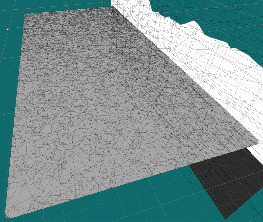
That being said, we're not totally finished with GenerateMesh. There are parts I haven't mentioned yet, because there will be some traps on the road. I'll talk about them when we'll get there, and we'll update the method then.
Also what about the colors? We haven't touched the list in the code! Do we even need vertices colors? It's true, color will be handled by the shader, not the color values of the vertex. So in theory we could leave it empty. But you'll see later that we actually will need it for something. For now, just remember it as an empty list.
Now, it's time we shape our mountains!
Step 2: Terrain
Using Unity's Shader Graph, we''ll write a vertex shader to change the position of our plane's vertex, so that it forms a terrain. Make sure Shader Graph is activated on your project. Then create a new Shader Graph in your assets (Right Click > Create > Shader Graph > Universal > Lit), and then create a Material that uses it (right click on the shader graph, Create > Material). Apply this Material to your plane. The changes you'll made to the shader will be visible every time you save it.
The first step is to move the vertices using an input. Here is how to do it:
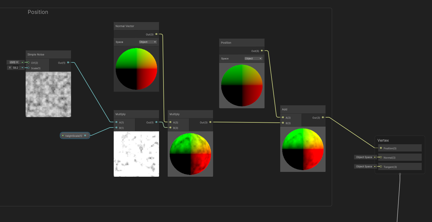
We use a (temporary) noise as texture, and multiply it to a float input mountainHeight that will determine how tall our mountain will be. Then we multiply the mesh's normal (the directions of the planes) with it, and add the result to the vertex positions. Then we set those positions as new positions. With this, you can deform a mesh in a lot of ways. Another solution could be to just move the positions on the Y axis. After all, we just want to increase the height here. But I prefer this method, because it's compatible with several kind of meshes. Since it uses the model's normal rather than a static Y axis, it can be applied to curves or even sphere!
Now while a Perlin Noise ("Simplex Noise") could be enough, our mountains will be more interesting with a more sophisticated noise. To quote Bob Ross: Everybody needs a friend, even noises! So we'll mix several noises together to create a unique rich texture. I created a sub-graph dedicated to it:
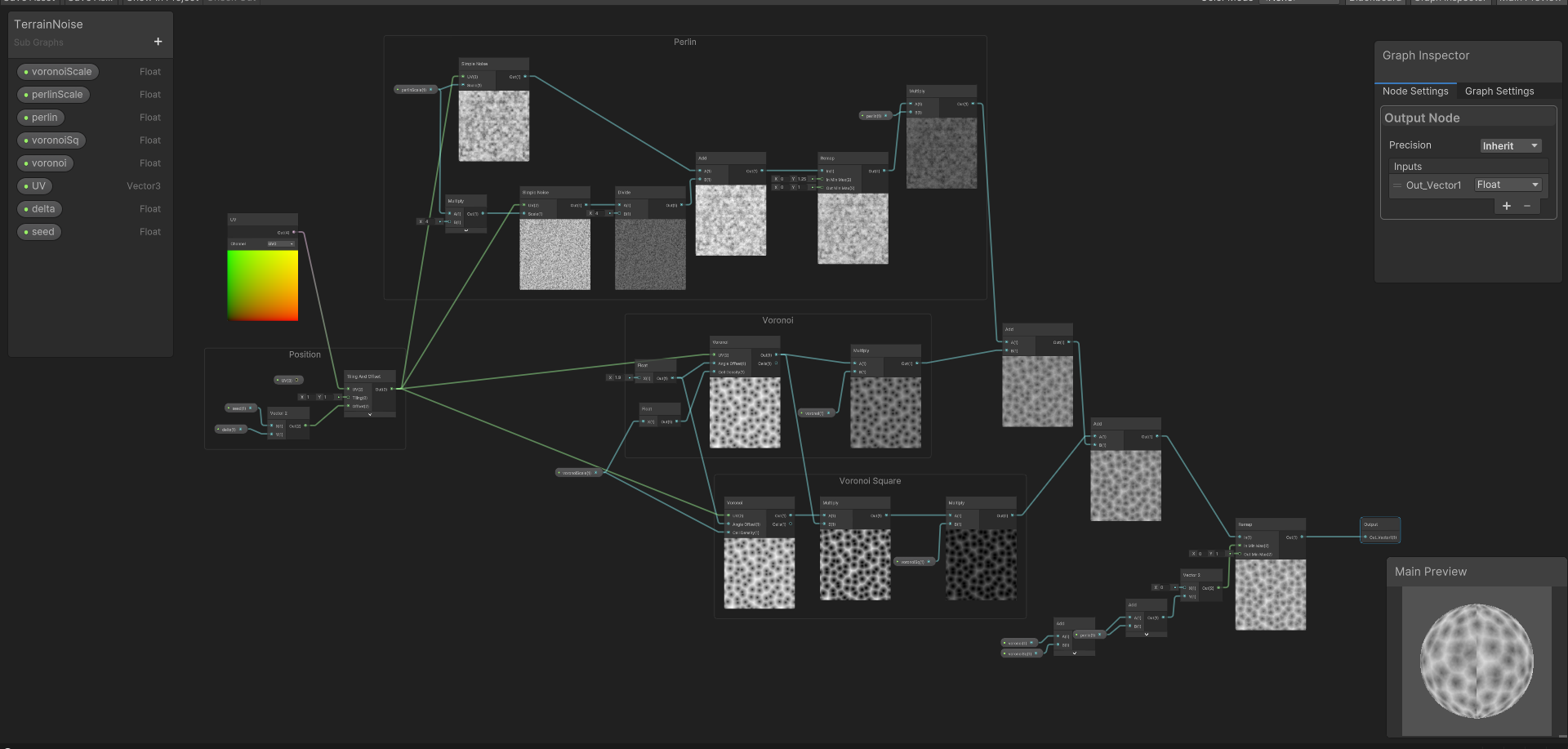
What this one does is mixing a Voronoi Noise with a Squared Voronoi Noise and a Perlin Noise. Each one of these has a ratio input (respectively voronoi, voronoiSq and perlin) that determines how much of it there is in the mix. For example, if I want more Voronoi than Perlin, I could set them to 0.6, 0.33, and 0.2. There's a lot of different texture you can create, that can result in all sort of terrain! I'll show you mine as example, but you should definitely experiment and try different combinations. You'll see that it's a really fun exercise!
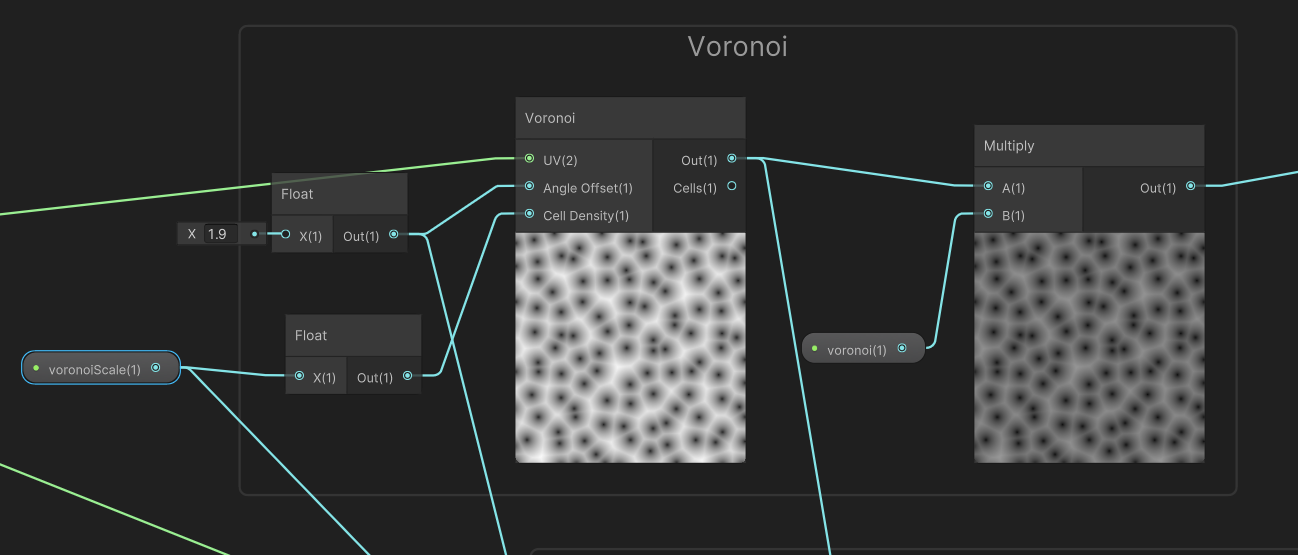
First, this is the Voronoi part. Nothing special here. I like Voronoi for mountains, because it creates shapes that look like valleys. As I said, it uses the "voronoi" input at the end to set how much there will be in the final mix. It also has a voronoiScale input that set the size of the cells in the noise.
Then there is the Squared Voronoi. This is just like Voronoi, but with more steep slopes. It's useful for tracing really clear mountains! I don't want the peaks to be too thin though, so I mix it with regular Voronoi to obtain something nice. Its recipe is pretty simple: it's the same Voronoi noise, multiplied by itself!

Then comes the Perlin Noise, that I use to create irregularities in the final result. Just like the Voronoi Noise, it has a perlinScale input to define how large the texutre is. However it also uses a common trick for creating noises: octaves. Instead of taking the Perlin Noise alone, we mix it with a smaller version of itself (here 4 times smaller) that has a lower intensity (4 again, or rather 1/4). This allows the noise to have smaller details and some grains, even when you use a large scale. I only added one octave, but you can repeat the operation several time for more details. Also I used 4 as a constant for the scale and the intensity of the octave, but there's nothing preventing you trying different values. The important thing is that each octave should be smaller and less intense than the previous one.

You might also notice the Remap I use after making the sum of the octave. In fact, I use the same method when adding the three noises together: I add them, and then pass the result through a Remap:
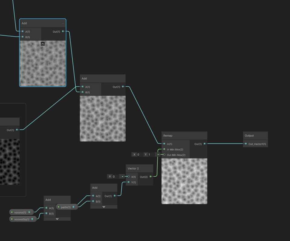
What that Remap does is ensuring that the result is comprised between 0 and 1. This is very important, because otherwise the height of the mountain will change every time you will update the amount of voronoi, voronoiSq or perlin. But this isn't what these input should do, and it becomes a nightmare to balance with mountainScale. So to be sure that the mountains keep the same heights no matter how much these values are, we use this Remap that takes the result of our addition, and rewrite it between 0 and 1. However it needs an Input min and Input max to be able to do so. Input min is still zero, easy. As for Input max, it's the sum of the max values of each of our noises: voronoi + voronoiSq + perlin. For example with the values I mentioned above, it would be 0.6 + 0.33 + 0.2 = 1.13. Same logic is applied for the Perlin Octaves : 1 + 1 ∕ 4 = 1.25.
If you want to create your own texture, the only part you must remember is this last one: add them together, and put them into a Remap. This will allow you yo try several mixes by manually changing the shader's input, while keeping the same mountain's heights!

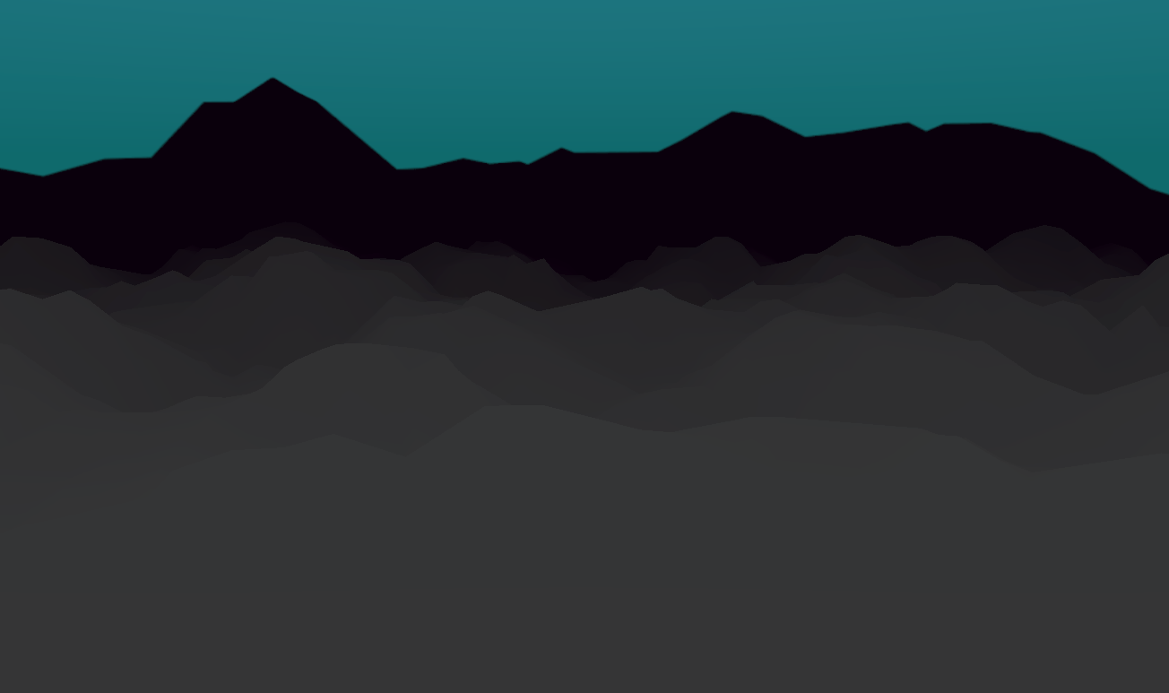
Okay, we have our mountains! But… It doesn't look low-poly at all! Where are our triangles?
This is because the normal maps are smoothed by default, and so the meshes faces become invisible. This is handy for rendering a sphere without millions of polygons, but not really helpful for what we want to achieve. How can we fix it? We need to update the normal maps in the fragment shader. And for this, here is a simple trick that you can use in any shader to make it look sharp:
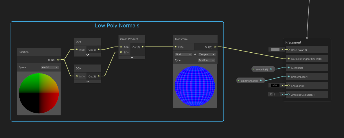
What does this do? And what are DDX and DDY? Those two elements are utilities provided by Unity Shader Graph. As you know, a shader operates pixel by pixel. However DDX and DDY allows to cheat a bit, because they compare the value of the current pixel with the previous one (respectively on the X axis and the Y axis). Here, used with positions (we are in the fragment shader, so those positions are the results of the vertex displacement), we obtain the difference between the previous position and the current one, which is two vectors parallel to the surface's slope (on X and Y). The cross product between those two vectors gives us… the normal of the current face! It's a normal in World position though, so we have to transform it into a tangent position so that it can be used as a normal map. It's a pretty lengthy subject, so if you want to learn more, you can watch this video.
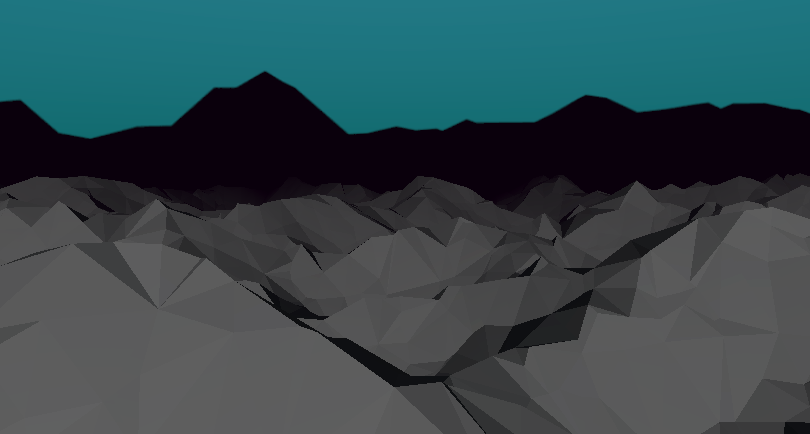
And thus we have low-poly mountains with a custom noise, that we can edit through the material's input, and even animate!
But wait! There's a catch on which it is very easy to trip. Look at what happen when we move the plane around the camera:
Hey! Why does it disappear? It's still in the frame, and in the editor we can clearly see that the plane is still there! What's happening here is Unity's Occlusion Culling, and it's a real rabbit hole. I'll try to make it short.
Unity uses culling to optimise what it has to render. Models that goes outside the frame of the camera are not rendered. Reasonable enough. However, the culling is calculated before the vertex shader are applied. And thus, our flat plane is indeed detected as outside the frame, and it's only afterward that the vertex shader modifies it and make it back into the frame again! But it's too late by then: it's not rendered anymore, and it disappears.
How can it be fixed? Should we disable occlusion culling? Fortunately, no, there is a solution. Unity uses mesh's bounds to determine if it is still in the frame or not. And we can modify these in the code! If you created the plane by code following this tutorial, these lines should be added at the very end of the GenerateMesh function. Otherwise, it's time for you to initialize a Component and apply modification to your existing model.
GetComponent<meshrenderer>().bounds = new Bounds(
  new Vector3(terrainConfig.sizeX / 2, 0f, terrainConfig.sizeY / 2),
  new Vector3(terrainConfig.sizeX, 100f, terrainConfig.sizeY)
);
Our bounds don't need to strictly follow the shape of the terrain. We just create a big box, as long and large as our plane. Then we just set a height high enough so that it will still be in the frame while moving the camera close. It's invisible in the scene. But thanks to it, the mountains don't disappear anymore!
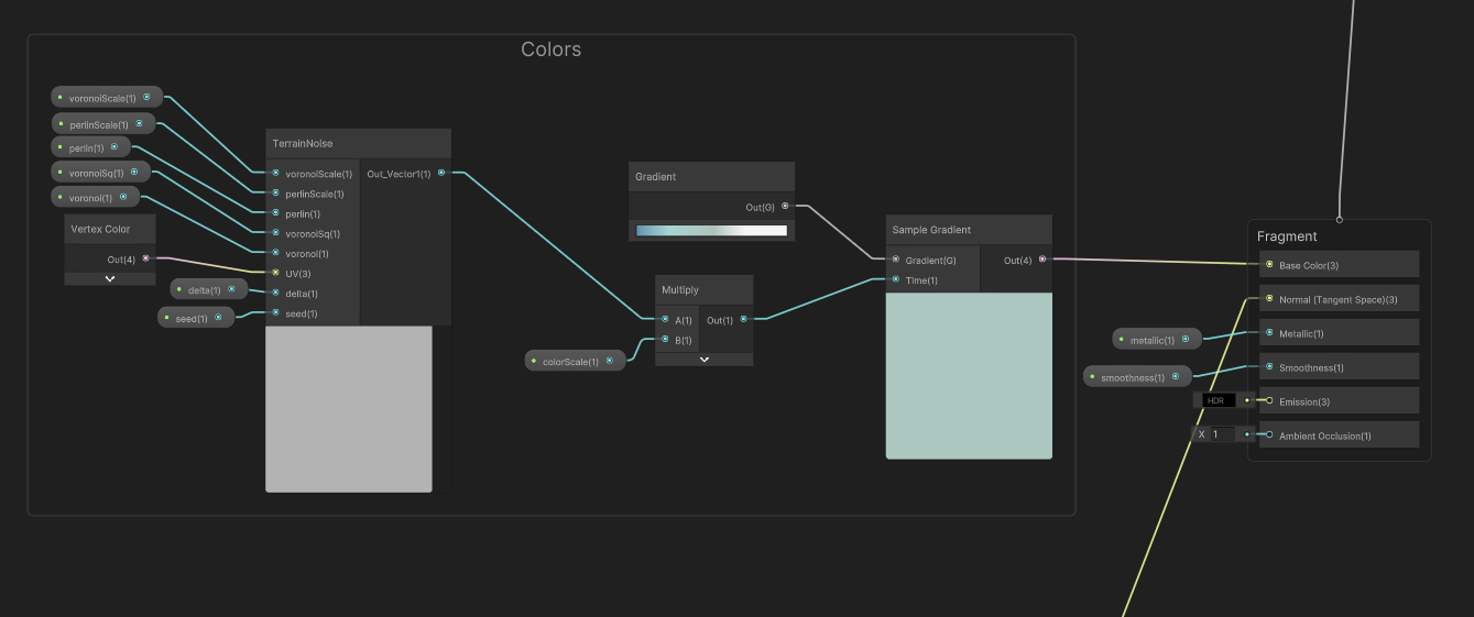
Step 3: Colors
The last step now is to apply colors to the mesh, based on the height. The objective is to use a gradient to paint the terrain according to heights: white on top, blue on the bottom, and kinda green in the middle. Naturally you're free to use your own colors.
The solution seems trivial at first. Use the same noise that you made for the heights, and use it as input of a Gradient Map in the shader. Unfortunately you can't set a gradient as Shader Input, so you have to define it inside the shader itself. Then plug the result to the albedo color output. Easy, right?
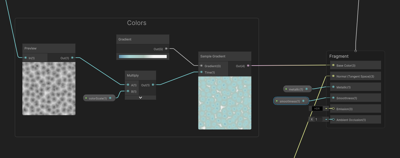
I also use a colorScale parameter that tells if the shader must read the entirety of the gradient, or just the lowest values. Useful for me to start with a flat terrain, and make it rise in real time.
That works, but if you do so, here is what you obtain:
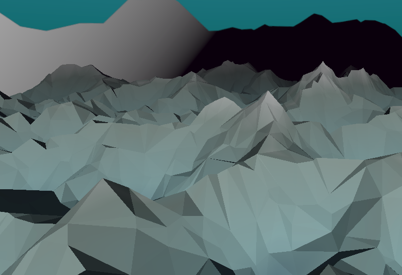
It's not bad, but... We want a low-poly look. And this means that we want only a single color on each face. These smooth gradients won't do at all! How could we change our shader so that it's coloring each face one by one, instead of every pixels?
I'll cut it short: you can't. It's not possible with just a shader. Trust me, I searched for a perfect solution. Using DDX and DDY, passing the vertex positions from the vertex shader to the fragment shader, or using the normals… But nope, nothing. If there is a solution to this conundrum, it's unknown to a most people. The fragment shader just doesn't have access to the position of the current face.
But we can give it that info from the code! Using a convenient canal: vertex color. Remember that? If we color the vertex to draw a single color on each face, which would contain the coordinates of the triangle, then we can use it in the shader to apply the final colors!
So let's head back to the mesh generation code. Once again, if you use an existing model, you must edit it to set its vertices colors. The logic shouldn't be too far from what I'll describe here.
We will define a GetTriangleUV method that takes a Triangle as parameter (a set of 3 points), and return a single position on the X/Y axis. Which could be a Vector 2, but since we're manipulating vertex colors inside a shader, it'll have to be a Color. First, let's write where we will call that method. Inside GenerateMesh, at the end of the loop on triangles, just before we add the normals, we also add the computed color:
var triangleUV = GetTriangleUV(triangle);
foreach (int x in Enumerable.Range(0,3))
{
  normals.Add(normal);
  colors.Add(triangleUV);
}
Setting the same color for each vertex of the triangle will ensure that the face has one single color.
Now, what should be written inside GetTriangleUV? Pretty basic: to determine the position of the face, I take the average position of its vertex. I just learned that this is called the "centroid" of the triangle! That's not the only solution though, you could also decide to take the lowest point or the highest. Whatever suits your needs. At the end, you must return a Color that works like a Vector 3. Set the X and Y value, and ignore Z. Make sure to divide the coordinates by the plane width and length so that the cordinates are written between 0 and 1!
private Color GetTriangleUV(Triangle triangle) {
  float triangleX = (triangle.GetVertex(0).X + triangle.GetVertex(1).X + triangle.GetVertex(2).X) / (3 * terrainConfig.sizeX);
  float triangleY = (triangle.GetVertex(0).Y + triangle.GetVertex(1).Y + triangle.GetVertex(2).Y) / (3 * terrainConfig.sizeY);
  return new Color(triangleX, triangleY, 0f);
}
If we just connect the Vertex Color to the Albedo Color, this is how it should look:

It'slike a UV gradient, but with one single color on each face! We can now use the vertex Color as UV inside the shader, so that the generated noise is aligned with the faces.
Note that this is why I put the noise function into a separate sub-graph. We need two in our global shader: one inside the vertex shader that uses the regular UV, and another in the fragment shader that reads UV from the vertex color.
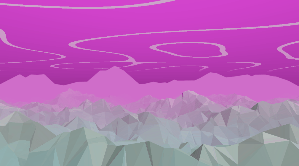
And thus we obtain the final result: low-poly mountains, colored by height! Managed mostly by shaders, and just a pinch of logic!
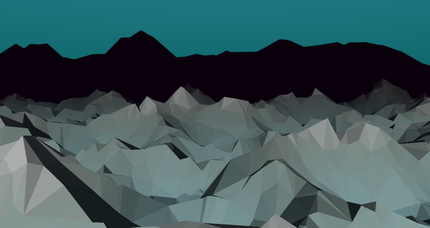
And once again, it can be animated just by editing the Material, to create neat effects without any cost on the CPU.
Conclusion
I hope this tutorial will be helpful for you. Above letting you shape mountains with my method, I mostly wanted to inspire you to use Unity's Shader Graph with more ease. With these techniques, you should be pretty versatile in what you can create with vertex shaders, and you know some of the pitfalls to avoid!
As for Sound Horizons, you might have see the new devlog video I shared on top of this post! It showcases how the environments were made, and what were my inspirations. Now that the environments are finished, and the game runs smoothly once again, my next goal is still to code the end of the level. I've already written the short music part dedicated to it. So now it's only a question of implementing it in Wwise, then coding in for Unity, and adding some new visual effects for it. See you then!
Leave a comment
Log in with itch.io to leave a comment.